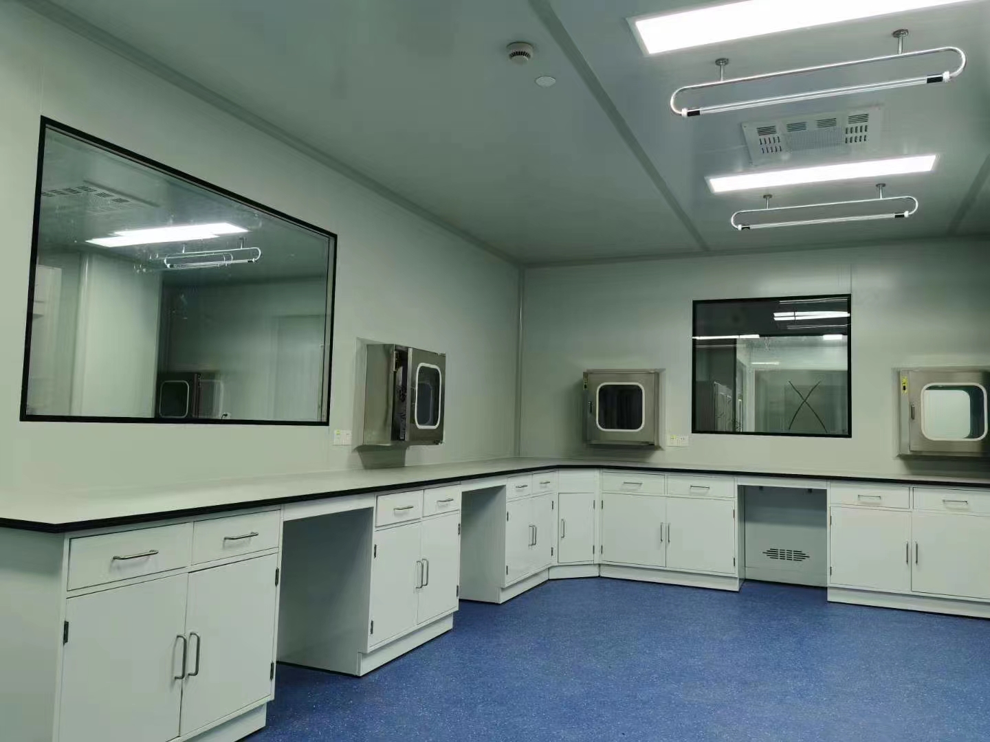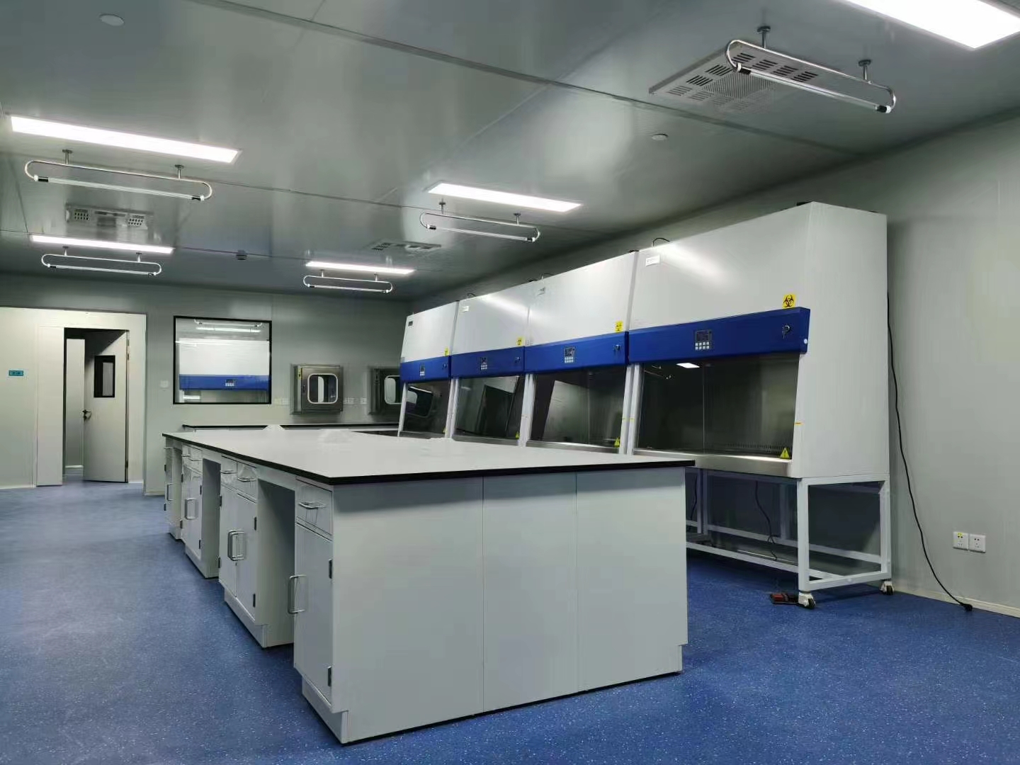

The chip yield rate in the IC manufacturing industry is closely related to the size and number of air particles deposited on the chip. A good airflow organization can take the particles generated by the dust source away from the clean room to ensure the cleanliness of the clean room, that is, the airflow organization in clean room plays a vital role in the yield rate of IC production. The design of the airflow organization in clean room needs to achieve the following goals: reduce or eliminate the eddy current in the flow field to avoid the retention of harmful particles; maintain an appropriate positive pressure gradient to prevent cross contamination.
Airflow force
According to the clean room principle, the forces acting on the particles include mass force, molecular force, attraction between particles, airflow force, etc.
Airflow force: refers to the force of the airflow caused by the delivery, return airflow, thermal convection airflow, artificial stirring, and other airflows with a certain flow rate to carry the particles. For the technical control of clean room environment, airflow force is the most important factor.
Experiments have shown that in airflow movement, the particles follow the airflow movement at almost the same speed. The state of the particles in the air is determined by the airflow distribution. The airflows that affect indoor particles mainly include: air supply airflow (including primary airflow and secondary airflow), airflow and thermal convection airflow caused by people walking, and the airflow caused by process operation and industrial equipment. Different air supply methods, speed interfaces, operators and industrial equipment, and induced phenomena in clean rooms are all factors affecting the cleanliness level.
Factors affecting airflow organization
1. The influence of air supply method
(1). Air supply speed
To ensure uniform airflow, the air supply speed must be uniform in a unidirectional clean room; the dead zone of the air supply surface must be small; and the pressure drop in the ULPA must also be uniform.
Uniform air supply speed: that is, the unevenness of the airflow is controlled within ±20%.
Less dead zone on the air supply surface: not only should the plane area of the ULPA frame be reduced, but more importantly, modular FFU should be adopted to simplify the redundant frame.
To ensure vertical unidirectional airflow, the pressure drop selection of the filter is also very important, requiring that the pressure loss in the filter cannot deviate.
(2). Comparison between FFU system and axial flow fan system
FFU is an air supply unit with a fan and a filter (ULPA). After the air is sucked in by the centrifugal fan of FFU, the dynamic pressure is converted into static pressure in air duct and blown out evenly by ULPA. The air supply pressure on the ceiling is negative pressure, so that no dust will leak into the clean room when the filter is replaced. Experiments have shown that the FFU system is superior to the axial flow fan system in terms of air outlet uniformity, airflow parallelism and ventilation efficiency index. This is because the airflow parallelism of the FFU system is better. The use of the FFU system can make the airflow in the clean room better organized.
(3). The influence of FFU's own structure
FFU is mainly composed of fans, filters, airflow guide devices and other components. The ultra-high efficiency filter ULPA is the most important guarantee for whether the clean room can achieve the required cleanliness of the design. The material of the filter will also affect the uniformity of the flow field. When a coarse filter material or a laminar flow plate is added to the filter outlet, the outlet flow field can be easily made uniform.
2. Impact of different speed interfaces of cleanliness
In the same clean room, between the working area and non-working area of vertical unidirectional flow, due to the difference in air speed at the ULPA outlet, a mixed vortex effect will be generated at the interface, and this interface will become a turbulent air flow zone with particularly high air turbulence intensity. Particles may be transmitted to the surface of the equipment and contaminate the equipment and wafers.
3. Impact of staff and equipment
When the clean room is empty, the air flow characteristics in the room generally meet the design requirements. Once the equipment enters the clean room, personnel move and products are transmitted, there will inevitably be obstacles to the air flow organization. For example, at the protruding corners or edges of the equipment, the gas will be diverted to form a turbulent zone, and the fluid in the zone is not easily carried away by the gas, thus causing pollution. At the same time, the surface of the equipment will heat up due to continuous operation, and the temperature gradient will cause a reflow zone near the machine, which will increase the accumulation of particles in the reflow zone. At the same time, the high temperature will easily cause the particles to escape. The dual effect aggravates the difficulty of controlling the overall vertical laminar cleanliness. The dust from the operators in the clean room is very easy to adhere to the wafers in these reflow zones.
4. Influence of return air floor
When the resistance of return air passing through the floor is different, a pressure difference will be generated, so that the air will flow in the direction of less resistance, and uniform airflow will not be obtained. The current popular design method is to use elevated floors. When the opening rate of elevated floors is 10%, the airflow velocity in the working height of the room can be evenly distributed. In addition, strict attention should be paid to cleaning work to reduce the pollution source of the floor.
5. Induction phenomenon
The so-called induction phenomenon refers to the phenomenon that the airflow in the opposite direction of the uniform flow is generated, and the dust generated in the room or the dust in the adjacent contaminated area is induced to the upwind side, so that the dust can contaminate the chip. The following are the possible induction phenomena:
(1). Blind plate
In a clean room with vertical unidirectional flow, due to the joints on the wall, there are generally large blind plates that will generate turbulence in the local return flow.
(2). Lamps
The lighting fixtures in the clean room will have a greater impact. Since the heat of fluorescent lamps causes the airflow to rise, there will be no turbulent area under the fluorescent lamps. Generally, the lamps in the clean room are designed in a teardrop shape to reduce the impact of the lamps on the airflow organization.
(3.) Gaps between walls
When there are gaps between partitions with different cleanliness levels or between partitions and ceilings, dust from the area with low cleanliness requirements can be transferred to the adjacent area with high cleanliness requirements.
(4). Distance between the machine and the floor or wall
If the gap between the machine and the floor or wall is very small, it will cause rebound turbulence. Therefore, leave a gap between the equipment and the wall and raise the machine to avoid letting the machine touch the ground directly.
Post time: Feb-05-2025

